Longitudinal Stress in Buried Pipelines near Bends or End Caps
Accurate estimation of the longitudinal stress is frequently required, such as during the engineering critical assessment (ECA) of girth welds or the integrity analysis of pipelines including defects with considerable circumferential extension.
At Kiefner and Associates, Inc. (Kiefner) (a Pipeline Engineering Consultancy company, and part of the Applus+ Group), we regularly address questions posed by our clients and members of industry. This article addresses questions related to longitudinal stress near the bends or end caps of buried pipelines during normal operation.
Are the stresses near a 90 degree bend higher than those near bends with other angles? Is 0.5 x hoop stress a conservative estimate of stress near a bend or an end cap?
Longitudinal stress, also known as the axial stress, generally causes less concern than the hoop stress for the integrity assessment of a pipeline due to its relatively low value when internal pressure is the primary loading condition. However, the longitudinal stress could be critical for special scenarios, such as
- engineering critical assessment (ECA) of girth weld
- fitness-for-service (FFS) analysis of metal loss with considerable circumferential extent
- susceptibility to circumferentially-oriented stress corrosion cracking
The integrity analysis in the scenarios above depends on accurate estimation of the longitudinal stress. In a straight buried pipeline segment under normal operation, the longitudinal stress is the sum of the component due to Poisson effect and the component due to thermal expansion. The equations to calculate these components have been provided in ASME B31.4 and B31.8. However, the longitudinal stress near a bend or an end cap is more complicated. At those structures, the internal pressure would generate thrust force. The thrust force in combination with the thermal deformation of the connected tangent leg(s) results in displacement at the bend or the end cap. The displacement at the bend generates both longitudinal movement and bending deformation in the connected tangent legs. The displacement at the end cap generates longitudinal movement in the connected pipeline segment. The deformation from those movements is restrained by the surrounding soil and diminishes gradually away from the bend or the end cap.
(a) Bend (b) End Cap
Figure 1. Thrust force due to internal pressure
Analytical solutions for longitudinal stress near a bend or an end cap under normal operation have been derived in a recent paper published in the Journal of Pipeline Engineering, June 2018 issue. The accuracy of the solutions has been verified by finite element analysis (FEA) as detailed in the paper. The analytical solutions enable the efficient calculation of stress at multiple bends or end caps and help to understand the influence of the bend or end cap to the longitudinal stress through sensitivity studies.
One interesting outcome from the analytical solutions is the examination of two simplified assumptions frequently used by the oil and gas pipeline industry.
- The stress near a 90° bend is higher than that near bends with other angles
- Stress near a bend can be conservatively estimated as one half of the hoop stress
Assumption I. The longitudinal stress near a bend consists of two components. One is from the bending of the tangent leg generated by the displacement at the bend and the resistance of the soil to the lateral movement of the pipe. The other is from the elongation of the tangent leg to accommodate the displacement at the bend which diminishes gradually along the leg under the friction of the soil. Figure 2 compares the stresses as well as each component near a 30° bend, a 45° bend and a 90° bend. The results were from a 30-inch diameter (OD) and 0.5-inch wall thickness (WT) pipeline operated at 2,000 psig pressure level. No thermal deformation was considered. As shown in the figure, the total stresses are higher near the 30° and 45° bends than those near the 90° bend at locations very close to the bend center. At locations away from the bend, however, the total stress near the 90° bend becomes the highest. A close look of the stress components reveals that the 30° and 45° bends generate higher bending components while the 90° bend always generates the highest elongation component. Figure 3 further shows the longitudinal stress just at the bend center with various angles. For the illustrated pipe dimension and buried condition, the stress at bend center reaches the highest value at around 40°. Such a trend is also verified by FEA shown as diamond points in the figure. Therefore, Assumption I is only true beyond a critical distance to the bend center. This critical distance depends on pipe dimensions, buried conditions and internal pressure level.
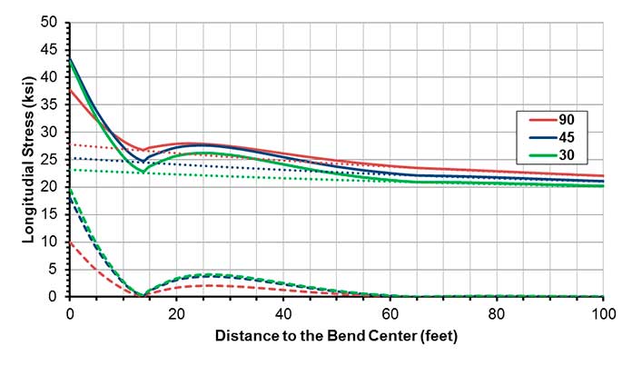
Figure 2. Longitudinal stress distribution along tangent leg with angles at the bend of 30°, 45° and 90°. The total stress (solid lines) consists of bending (dashed lines) and elongation components (dotted lines).
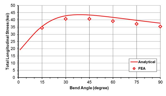
Figure 3. Longitudinal stress at bend center with various angles
Assumption II. The assumption of half hoop stress is based on the thrust force from internal pressure at a 90° bend without considering the resistance from the soil and the bending of the pipeline. For the pipeline investigated in Figures 2 and 3, half of the hoop stress is 30 ksi. From Figure 2, the total longitudinal stress is lower than 30 ksi at locations beyond 8 feet from the bend center. Most investigated girth welds or defects should be beyond 8 feet from the bend center in a 30-inch OD pipeline. However, exceptions exist such as when the defects exist on the curved portion of a bend or a girth weld connecting a pipe joint to a segmented bend is present. The elongation component is uniform in the pipe cross section and never exceeds the 30 ksi. However, the total stress may exceed the 30 ksi near the bend center after adding the bending component. If the defect is close to the neutral axis of the bending, the overall stress may still be below half of the hoop stress. In summary, one half of the hoop stress is conservative at most locations away from the bend. For girth welds or defects near the bend center, the stress should be examined with the consideration for the defect location along the pipe circumference.
This article is based on a technical paper written by Fan Zhang PhD and Michael Rosenfeld PE and published in the June 2018 issue of Journal of Pipeline Engineering. The paper includes the details of the analytical solution, and its derivation and FEA verification. In addition to the examination of two simplified assumptions described above, the paper also discussed the influence of bend curvature and influenced length.
To discuss more on this topic, feel free to contact us.